
I have created a mesh network algorithm for embedded systems. This implementation is released be released under MIT License.
Me and a friend have started an Internet Of Things project and we wanted to have a radio module to our microcontroller for communication. The radio module we choose was the NRF24L01+.
One question might arise: Why not use the NRF24Mesh[1] solution that’s already been developed? I’ve looked at the design and noticed that it could be improved which are mentioned in the features, and I also wanted to create it by myself, because I can 🙂
In this post I will discuss about the architectural design of the Mesh Network.
Features of this implementation:
Address range: ~2^18 addresses (262144).
Decentralized network topology: a master is needed, all grouping and addressing will be decentralized, which means that the closest “parent” is responsible to address it’s children’s.
Mesh with multiple routes: All the nodes in the network has always a “default” route to master. Nodes can also pair to other nodes in the network that is physically close. If node A and node B needs to communicate with each other they don’t need to send the packet via the master node, if there is an opportunity to send the packet to a physically near node, and the number of hops is less than via the master, the packet will be sent to that neighbour, which will route it onwards.
Background
A brief background in networking.
Mesh Network Topology
There exists several commercial mesh networks, the most used is Zigbee, Bluetooth and Thread. They are Wireless Private Area Network (WPAN) and are described int the IEEE 802.15 standard.
A mesh network is able to route packets between nodes.
For example, Zigbee has three different network devices: Coordinator (Master), Router and End device. The master is also the router out of the Zigbee network to another network, such as Ethernet. A Router is node that is connected to a power outlet and the End device could be a sensor using a battery as a power source. The End device need to be power efficient and only use the radio as little as possible, therefore it will not route packets on behalf of other nodes.
Ethernet
Data link layer, layer two in OSI (Open Systems Interconnection model).
In order to send packets between nodes in an Ethernet based network, source and destination MAC (Media Access Control) addresses is used. A MAC address is six bytes long. If the destination MAC address is not found, the packet will not reach it’s destination.
Internet Protocol (IPV4)
The network layer, layer three in OSI. The IP layer enables routing of packets. A source and destination address is in the IP header. All devices using IP have a routing table. Most often only one route is defined, which is the default route. But other routes can be added. Routes must be in the same network address space as the device who will be using it. Routes is configured with IP address in the routing table, not MAC addresses.
For example, NodeA want to send a packet routed via NodeB to NodeC. Firstly, NodeA will do a ARP (Address Resolution Protocol) broadcast to get the MAC address for the IP address of NodeB. When the response arrives, NodeA sets the NodeB MAC address as the destination and sends the ethernet packet on the physical layer. NodeB will look in it’s routing table to see which router that know the IP address space that NodeC reside in. If the IP address network of NodeC is not known in NodeB, it will send the packet via the default route.
NRF24L01+
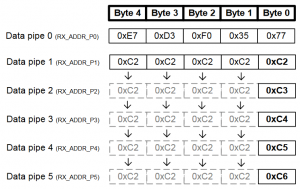
The radio has MultiCeiver (chapter 7.7) technology which means that it can receive packets from six different addresses (data pipes). Data pipe 0 address is five bytes. Data pipe 1-5 share the same network address space and have different host addresses. See figure 1 for the address configuration of data pipes.

Mesh design
The mesh network is aimed to be hardware agnostic. For this project the microcontroller is an STM32F103C6T8 and the radio module is NRF24L01. The code is written in C++. The mesh implementation is portable to other radio modules but some minor modifications is needed. A plus in the NRF24L01 is that the radio can utilize a broadcast address.
Network addressing
In NRF24L01 case, the network address is four bytes and the host address is one byte. One byte is equal to eight bits. In the best case all network- and host addresses can be utilized. If all bytes could be used, the address space would be 2^(5*8) = 2^(40).
There is six data pipes addressable in the radio module. One will be used for broadcast and the others will be used for communicating with other nodes in the network.
If MultiCeiver technology is enabled in the radio module, each node can connect to five other nodes and use broadcast in an power efficient way. Five nodes will be connected to master. Every child will have a data pipe to their parent and maximum four children connected.
Master addressing:
Data pipe 0: Broadcast address
Data pipe 1: Child node 1
Data pipe 2: Child node 2
Data pipe 3: Child node 3
Data pipe 4: Child node 4
Data pipe 5: Child node 5
Child node 1 addressing:
Data pipe 0: Broadcast address
Data pipe 1: Master
Data pipe 2: Child node 1_1
Data pipe 3: Child node 1_2
Data pipe 4: Child node 1_3
Data pipe 5: Child node 1_4
Child node 1_1 addressing:
Data pipe 0: Broadcast address
Data pipe 1: Child node 1
Data pipe 2: Child node 1_1_1
Data pipe 3: Child node 1_1_2
Data pipe 4: Child node 1_1_3
Data pipe 5: Child node 1_1_4
And so on.
In every network segment there is maximum five nodes that need an address. The address range between node is 1-5. Three bits can address 8 nodes (2^3 = 8). The total number of the network address is 32 bits. If 3*9 = 27 bits is used for network addressing, the node tree will be nine levels deep, there is also 5 spare bits that can be used for various things.
The addressing struct is shown in figure 3.

If a broadcast message is sent, the broadcast bit is set to one, if master is sending a packet the master bit is set to one, if a node is not paired to the network, the gen_addr bit is set to one and all the net_bits and host_addr is randomized. Two bits is unused and can be used for various settings in the future.
Messages
There will be various messages sent between the nodes, in order to differentiate between them, all packets have a header see figure 4.

The msgno field in the header describes which packet that is being sent or received. When a node is sending, the req (request) message is used, and the responding packet is a rsp (response), see figure 5 for the different packets that can be sent and received.

In figure 6, the union contains all struct messages that can be send and received in the network.

Associating nodes
When the nodes starts, they will periodically send out broadcast associate packets. When the master node has started, it will respond to the packets with an associate respond packet to the generated nodes address (the address will have the gen_addr bit set). When the node has received the respond packet, it sends a network_assignment request. The master will respond with a network_assignment respond containing an address to the node. Now the node is assigned to the master and will send a register_to_master request to the master, which the master will respond with a register_to_master respond. When a node has been registered to the network, it can also respond to broadcast associate requests, building a new network segment.
The first node (NodeA) attached to master will have the address:
net_bits[0].net = 0x01
net_bits[1].net = 0x00
net_bits[2].net = 0x00
net_bits[3].net = 0x00
net_bits[4].net = 0x00
net_bits[5].net = 0x00
net_bits[6].net = 0x00
net_bits[7].net = 0x00
net_bits[8].net = 0x00
If the second node (NodeB) registers to NodeA, the address will be:
net_bits[0].net = 0x01
net_bits[1].net = 0x01
net_bits[2].net = 0x00
net_bits[3].net = 0x00
net_bits[4].net = 0x00
net_bits[5].net = 0x00
net_bits[6].net = 0x00
net_bits[7].net = 0x00
net_bits[8].net = 0x00
And so on.
Routing and Mesh
When the network has formed, routing of packets will work based on the network addresses. The parents will know their child networks and the children is able to send packets towards the master. The packets will flow upwards (towards the master) and downwards (towards a child). But nodes will also send out broadcast_neighbour requests, the physically near nodes will respond to the request. The requester will build a list of physically near nodes which don’t reside in the same network segment. This will enable the nodes to also talk sideways, forming a partially connected mesh network.
Conclusion
For building and testing the mesh algorithm Google Test has been used. NodeTest.h sets up a network nine levels deep and all children gets associated to the network. Project is ongoing and if you want to get involved please contact me, there is much fun left to be done! Next step will be to setup the network on actual hardware, for example with an Arduino or an STM32 microcontroller. The source code for mMesh[3] is available at Github.
References
[1] https://tmrh20.github.io/RF24Mesh/
[2] https://www.sparkfun.com/datasheets/Components/SMD/nRF24L01Pluss_Preliminary_Product_Specification_v1_0.pdf
[3] https://github.com/payano/mMesh