
This is my first encounter with the new microcontroller and programmer I ordered from aliexpress. The microcontroller is an STM32F103C8T6 and the programmer is a ST-Link v2 clone.
I’m thinking of creating a course for beginners to be able to use much more of the functionality from the STM32 microcontroller. I have created a new blog post for this topic and I want your feedback if this is a good idea and what you want me to cover in the course. The radio module is not set as well, feedback is welcome! Here is the link: Stm32f103 course on Udemy
The first thing to be done is go to http://www.openstm32.org/ and create an account. Download and install “Installing System Workbench for STM32 with installer“. Download and install STM32CubeMX.
To connect the microcontroller and the programmer i used this circuit diagram:
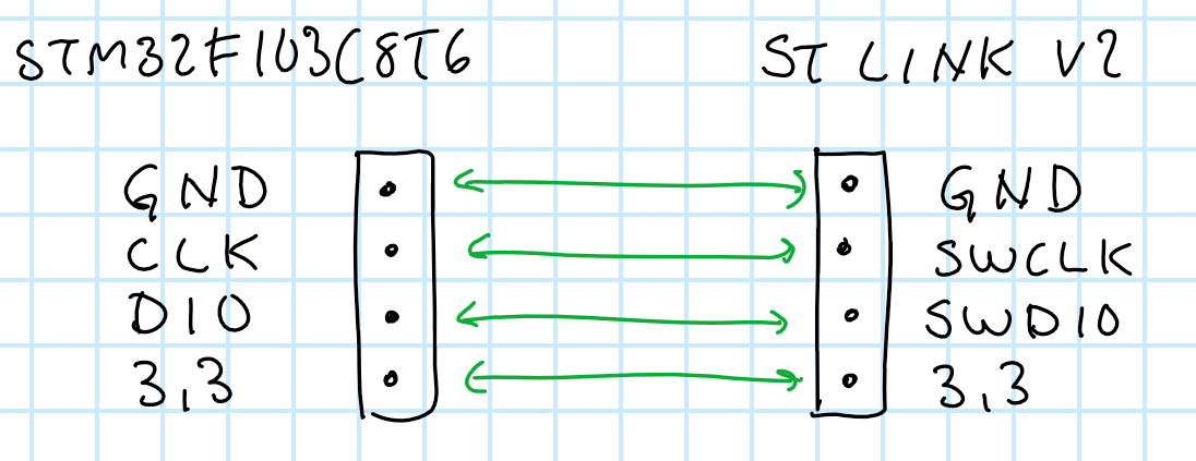
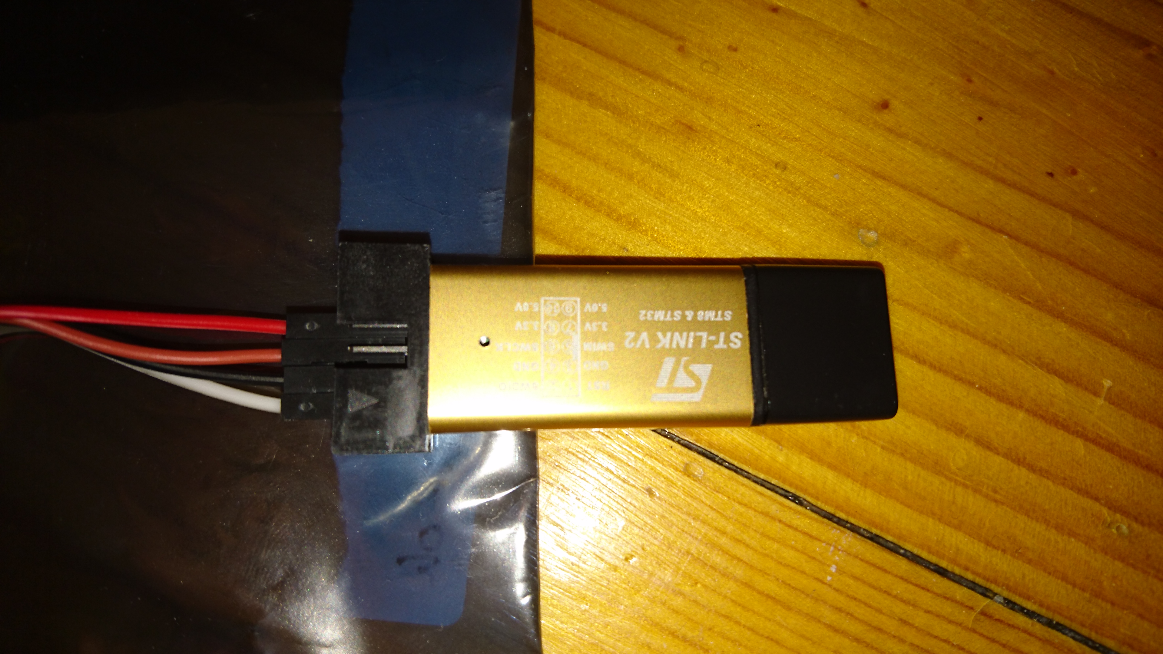
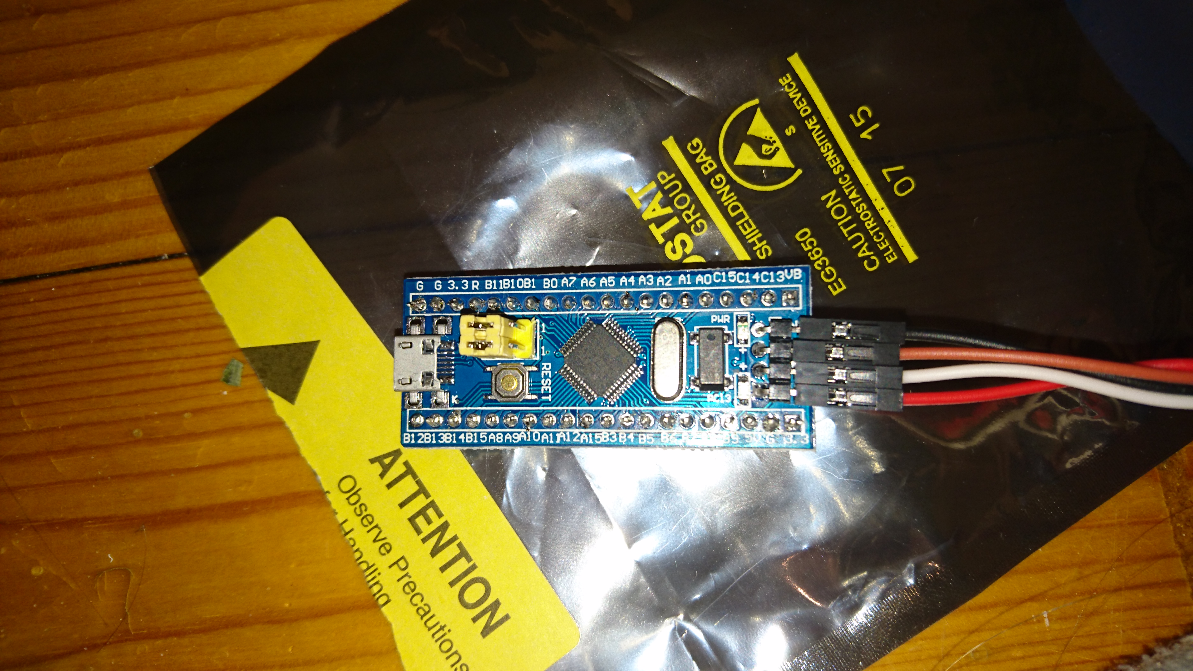
In reality it looks something like this:
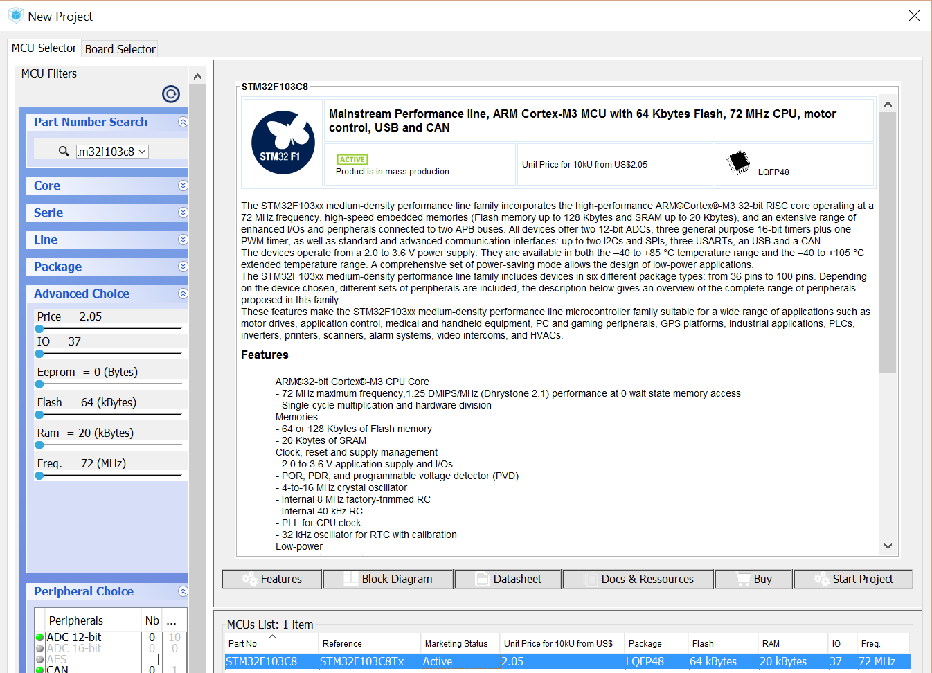
Open up STM32CubeMX and choose New Project.
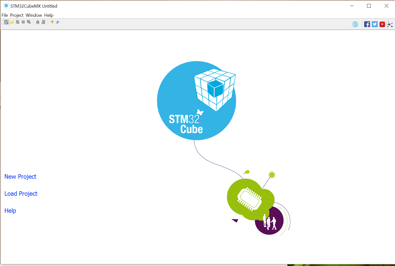
In part number search write: STM32F103C8T. Click on the microcontroller and press Start Project.
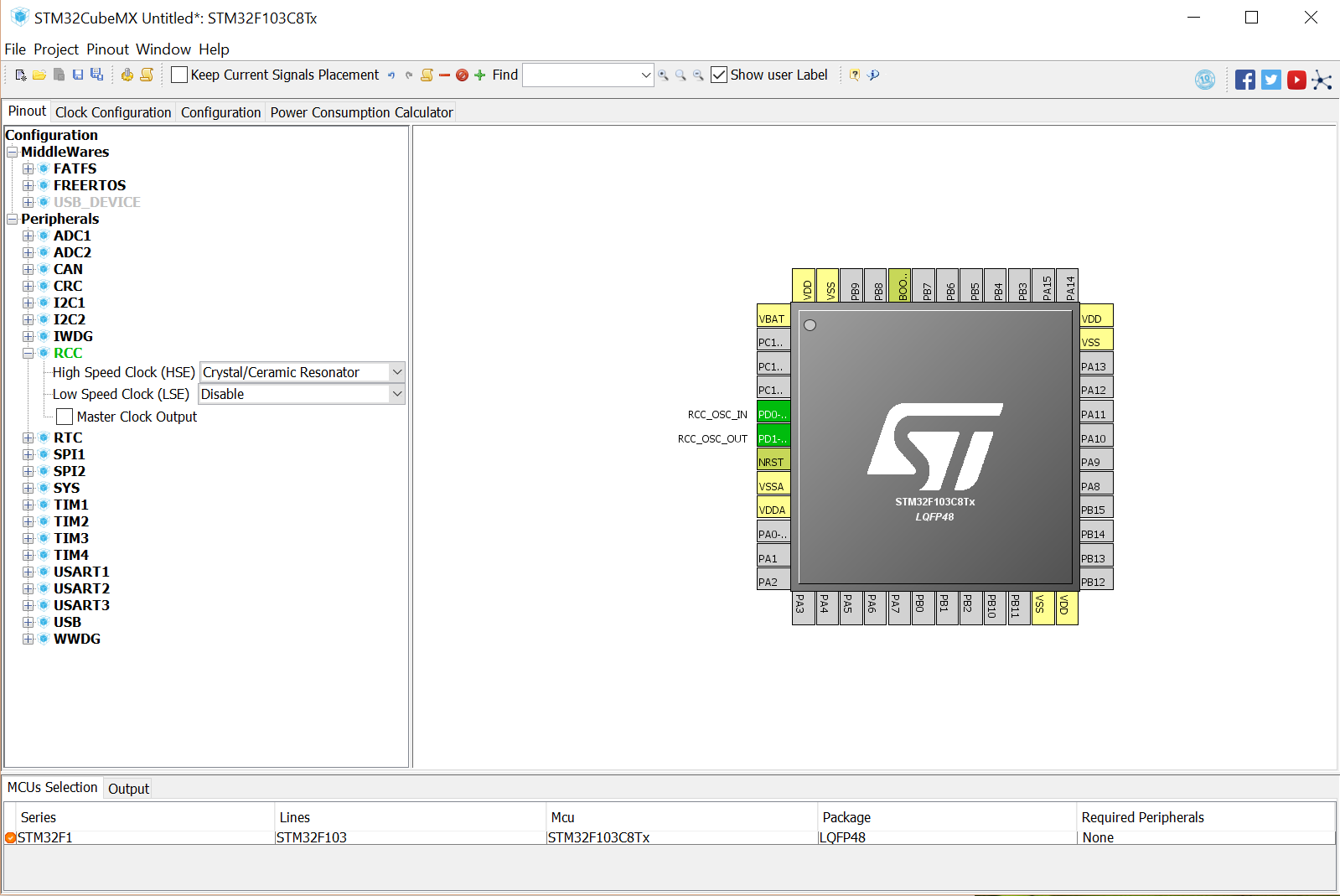
In Pinout configuration choose RCC, choose Crystal/Ceramic resonator in HSE (High Speed Clock).
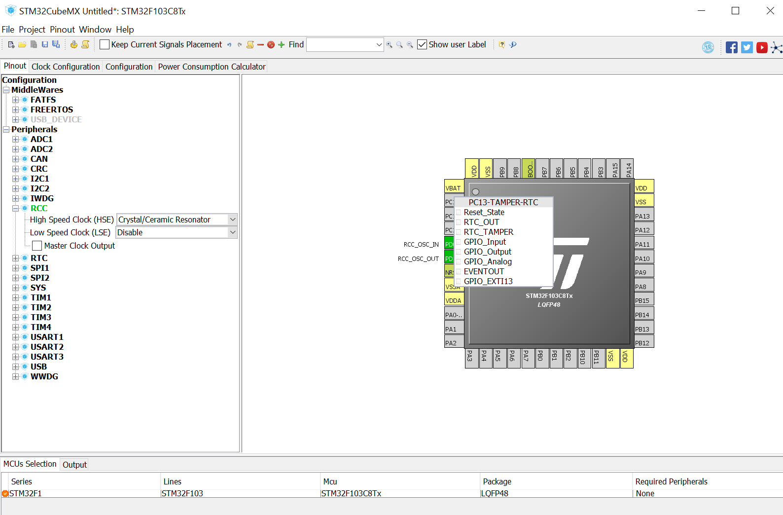
On the image of the microcontroller press on PC13 and choose GPIO_OUTPUT.
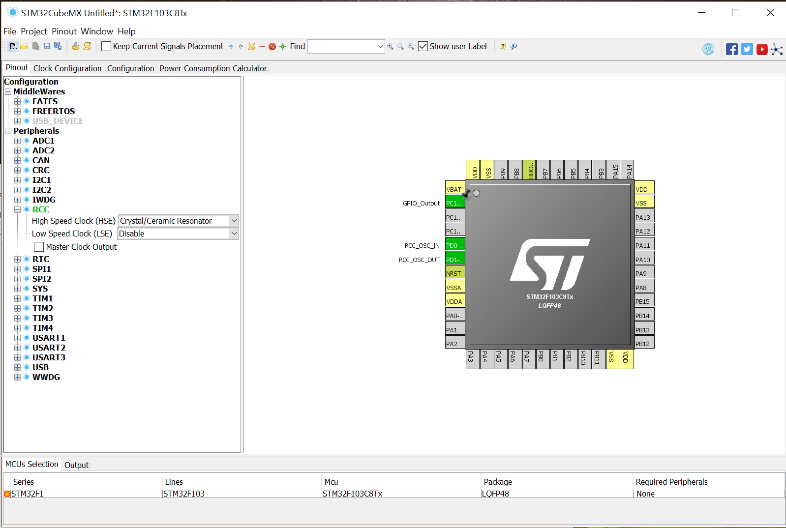
After it has been choosen it is now marked as green.
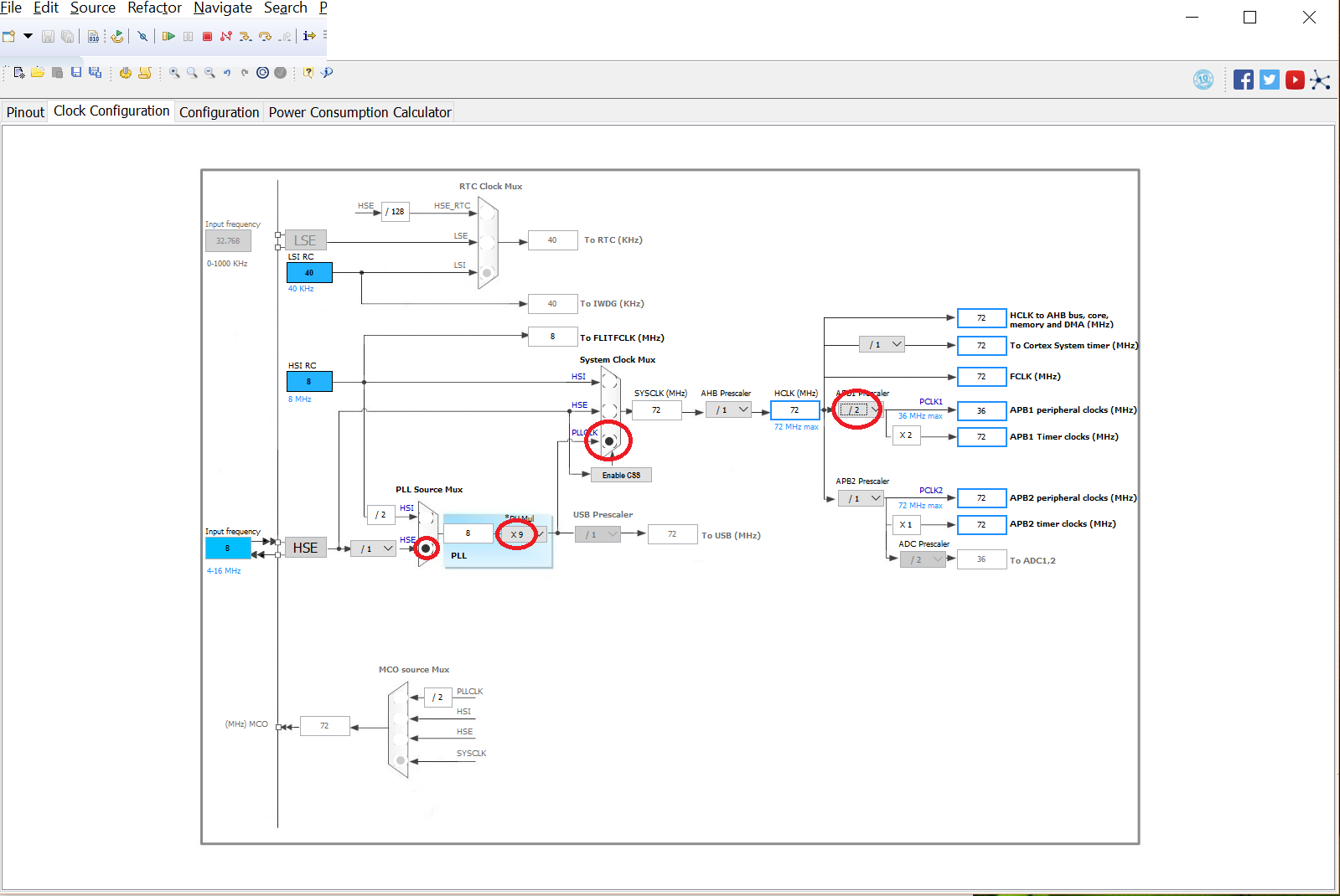
Go into Clock Configuration tab and choose the HSE clock for the microcontroller.
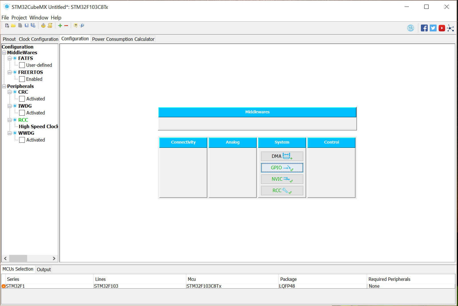
Go in to the tab Configuration and click on the GPIO menu.
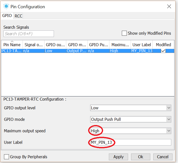
Set Maximum output speed to High and create a label for the GPIO pin. Press Ok and leave Pin Configuration.
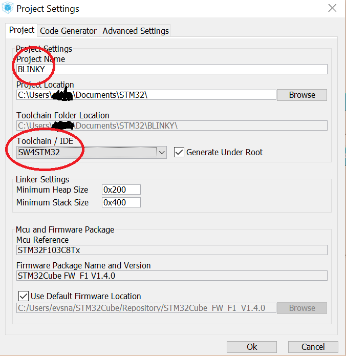
Under project, press Project Settings. Name your project to BLINKY and choose location. Under Toolchain/IDE choose SW4STM32. Press Ok.
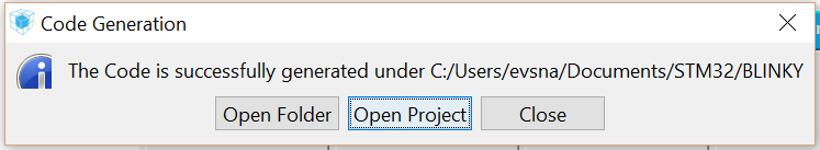
When code generation is done press Open Project.
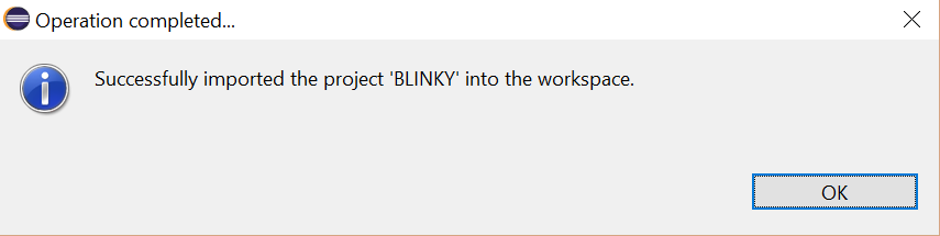
When Eclipse has opened and imported the project the Operation completed dialog should show up.
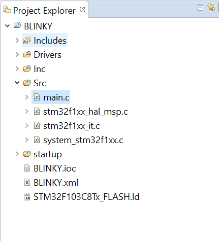
Under Project Explorer expand Src and double click on main.c
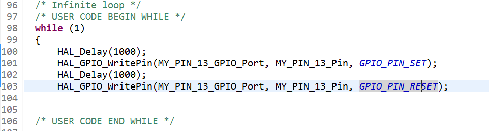
In the main function, in the while(1) loop write down these four and save main.c.
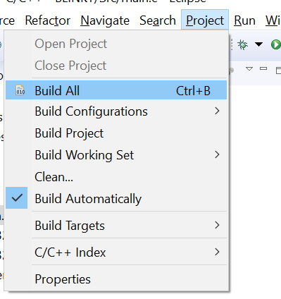
Under Project, press on ‘Build All’ or use the shortcut Ctrl+B.
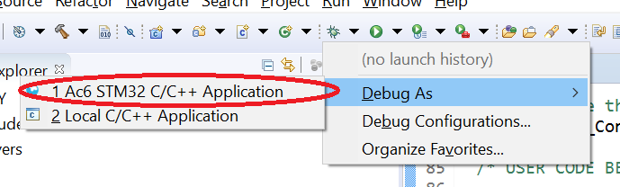
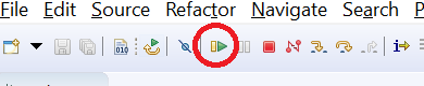
On the ‘bug’ symbol press on the down arrow, choose Debug As and Ac6 STM32 C/C++ Application.
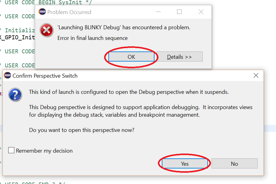
This will go wrong, no worries, this is always happening to me. This is because of a misconfiguration in the debugging profile. This will be handled now. Press Okey on the ‘Problem Occurred’ dialog window and choose yes in ‘Confirm Perspective Switch’ window.
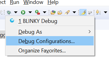
Press on down arrow symbol to the right of the bug and click on ‘Debug Configurations’.
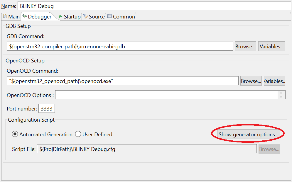
Go into ‘Debugger’ and click on ‘Show generator options…’
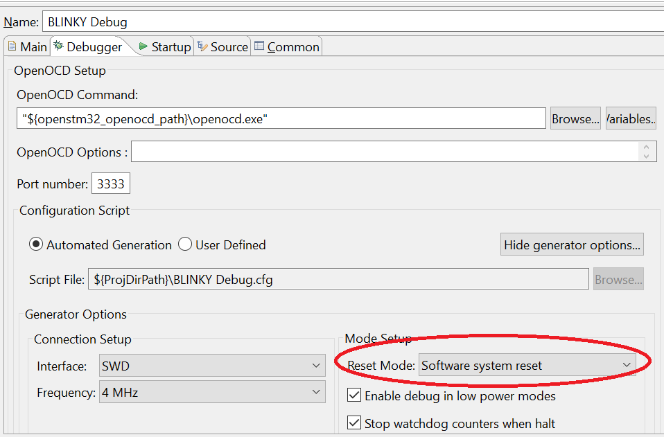
Use the ‘Software system reset’ as Reset mode.
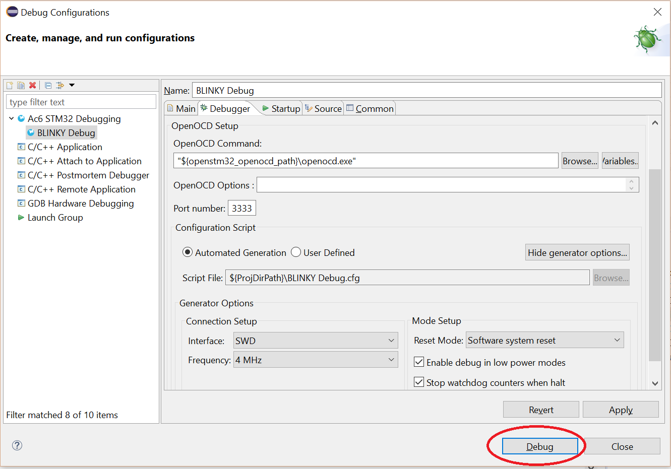
Press apply and the debugging now works. You can either choose to debug from the configuration menu or do it on the ‘bug’ symbol in the Eclipse workspace. Press debug
After the BLINKY program is compiled and sent to the microcontroller the last thing to do is start running the application. By default the debugger halts at the start of the main functiom. Press on the Play symbol in Eclipse to start running the program.
Sucess!! This is a video when running the blinky example project:
// With the new software from openstm32 and stm32cubemx, i didn’t get the software to run, it always crashed. After stepping through the code i could easily find out what row was making the stm32 controller to crash…
In the file: stm32f1xx_hal_msp.c on row: 77.
Comment out this line: __HAL_AFIO_REMAP_SWJ_DISABLE();
If you have trouble to start up the device and you get the error message: Wrong device detected.
Hold the reset button while pressing on the “bug” symbol in eclipse, wait for around one second after you pressed that button and release the reset button on the stm32 controller, now you should be able to program the controller again!
I hope this guide was helpful because it took me sometime to get it up and running.
Happy coding!
4 responses to “STM32F103C8T6 – ST-Link v2 – Blinky example”
Hello,
Thank you for this debugging solution which is the only one that works well for me.
I have two noob questions to ask you:
Have you found a solution to automate this with a local config file?
My ST LINK V2 Chinese has a RST pin that I connected to the nRST of my card and your solution works because it must be ignored by the soft. Have you tried using it ?.
Thanks
Rob
Hiya, I’m glad to hear that it worked out good for you.
I have not tried to automate this. I got it working and moved on and have not tested more on the subject. I have changed circuit and I am using stm32-nucleo and are not developing on this solution anymore.
Thank you for this solution.
searched 3 hours …..
You are welcome.